Final Design
Exceeding Your Expectations

Code for the Linear Actuator
We had difficulty with the code for the linear actuator: figuring out how to get the i statement to work. The biggest difficulty after setting up the i statement correctly and it still not working was realizing that we had to have an option to “cease all motor functions,” or have the linear actuator stop moving when the button wasn’t pushed down. An additional challenge then was adding a wireless connection to the code: the crutches communicate two piece of information between each other: the value of i, and whether or not the button is pushed down or not.
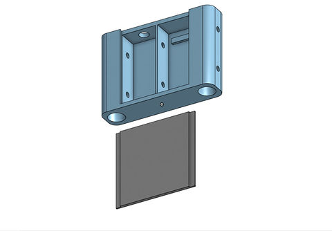
CAD
Our project would not have been possible without the 3D materials we printed to hold the crutch together. We printed and iterated on 3 different parts of the crutch using OnShape. We had difficulty sometimes with the 3D printers themselves: sometimes the print wouldn’t work and we’d have to restart. We had to have accurate measurements and spacing between the frame of the crutches and the linear actuators. As the project went along, we figured out the measurements that worked for the diameter and width of the crutch.
Final Product
Final Product at Design Expo
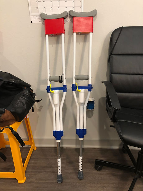
Our final product as a very polished finish that enhances the effort that was put into its design. We painted all of the 3D parts red and blue, and the frame of the crutch white. Our crutch used a soldered circuit board, Arduino Nano with transmitter, battery, and switch all tucked within the box at the top of the crutch. It has one smooth button attached on the right crutch for easy access, the wiring of which goes up through the hollow body of the crutch. We attached the original rubber base of the crutch back on to the end of the linear actuator, in addition to a hollowed out steel rod which we drilled holes in to conserve weight. Because we purchased the frame of the crutches and did not have to manufacture it, we spend less time in the machine shop than might have been expected. A lot of the manufacturing done for this project involved drilling holes and attaching all the parts.
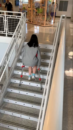
For the Design Expo at the ITLL, we had multiple pairs of batteries and Arduino Nanos to ensure against it failing. We had a successful Design Expo and were fortunate enough to win our section for many reasons, one being that we hit all our requirements. Our crutches fulfilled their purpose of making it easier to maneuver comfortably and efficiently to the varying needs of any user. We also were able to incorporate and iterate upon additional cushions for the top of the crutch. This addition showed that you can always be improving your product beyond functionality.
Design Expo and Testing
 |  |  |
|---|---|---|
 |  |
User Testing
Since our product is made to benefit the users, we decided that the best way to get feedback is to ask the people who will be using our product. We had anyone we could find test it out and give us some feedback. This also really benefited us during the iteration process because it gave us the opportunity to change our product in ways that we originally did not think of. For example, the button iteration was a part of our product that we got lots of feedback on. The change from two buttons to one was huge because it made it simpler for the user. Another part of the button iteration was the feel of the button on the hand. This is a small change that really changed our project by making the button more comfortable for the user. Overall, the user feedback was a huge part of this project because if the users did not like the product, it would not have been as successful.
User Interviews
Beam Equation
To calculate the sturdiness of the mount below the handle securing the linear actuator, we calculated the amount it would deflect under that max load that the linear actuator could take. For our purposes, we decided to use the simple beam equation to represent the deflection of the beam. The simple beam equation takes the elastic modulus of the material (PLA= 3.5 x 10⁹) and the second moment of area, or the area moment of inertia, I. This value of I is based off of the base of the beam across its support and the height of the beam. For a max load of 900 Newton’s or 225 lbs on each linear actuator, the PLA mount would bend .2 millimeters, a miniscule amount for the load put on it. Because of this equation, we can confidently say that each of our crutches can support the max load of the linear actuators.
_edited_edited.jpg)